|
The purpose of the head
gasket is more than just to create a seal between head and the deck of
the block.
It acts as
1) a guide for coolant
flow between the block and the head and
2) to promote heat
transfer between them.
The head itself is also
a conduit for coolant transfer to the radiator. Most older sportscars
use gaskets that are made from a sandwich of very thin copper, a
thicker fiber layer (typically asbestos laden) and thin steel. This
gasket design makes it difficult to personally customize for racing
applications and is inherently weak. It is also hazardous to your
health if broken and the fibers are aerosolized and inhaled.
Heat is produced by the
engine almost entirely at the combustion chamber. Coolant flows from
the radiator to the block where it is pre-heated before it goes to the
head where the temperatures are the greatest. The coolant then flows
through the head to the radiator where it looses heat. Water is the
heat sink of choice since it has the highest specific heat capacity.
In order for the coolant
to be functionally efficient it needs to move in-mass from the rear of
the head forward. Most engines have coolant holes in the gasket spaced
from one end to the other. These gaskets allow the coolant to percolate
through to the head less optimally. Generally, there are smaller
coolant holes in the gasket place forward which are needed primarily
for gaseous escape routes and less so for cooling purposes. Since
racing engines produce more heat it would seem intuitive that the flow
through the gasket be channeled to maximize cooling efficiency by
having more of the coolant flow through the rear of the head. It should
also be stated that the flow of the coolant has to be such that there
is an adequate dwell time within the head to adequetly absorb heat.
Additionally, the coolant should be free of any insulating contaminants
such as air (in the form of micro-bubbles) that would preclude ideal
heat conductance. Engines like to run efficiently at an optimal
temperature typically above 180F but less than 220F. Running an engine
hard prior to proper temperature is not good.
Torquing:
This can be a problem at
times. It is critical that the fasteners you are using are better than
"nominal". Use the best you can afford. A key factor that is not
considered often is that the fasteners not only hold down the head but
also PULL-UP on the block.
The torquing procedure
works in two locations
1) on the head side and
the
2) block side.
The threads within the
block maybe weak. Some spots within the block are weaker than others
-depending upon how much metal is around them. When these weaker spots
are stressed they "give" more than other areas. This can actually
deform the block and dimple the deck surface a bit. This
under-appreciated problem can create sealing dillemas. One method used
to mitigate against this effect is to study each motor and relieve
(chamfer) the holes where the fastener enters the block.
Bolt loading:
When a bolt is tightened
a large portion of the tightening torque is used to overcome the
resistance of the threads. Only about 20% (at most) of the torque is
transmitted in tension to the fastener. An important factor in this is
the surface finish of the threads. Some aftermarket fastener
manufatures coat the fastener with a laquer based material that
requires a high quality moly lubricant to be placed on the threads for
proper torquing. If this is not done improper tightening will occurr.
If you wish to use an oil on the threads for torquing - you need to
remove this coating with a wire brush.
EXCESSIVE bolt loading
will cause problems.
Many backyard mecanics
think that if 50 Ft. lbs of torque is good then 60 is better. In fact
dynomometer testing has shown that less is best in most instances.
Indeed extra horsepower maybe gotten by being "torque frugal". Why???
The more torque that is applied onto the block the more chance of
distortion. This distortion is usually seen at the weakest places at
the narrowes point of the bore and at the top of the cylinder. At the
top of the cylinder where the compression pressures are always greatest
any excess distortion will nullify any benefit of that extra clamping
force. Blow-by of gasses will cause premature gasket burn through and
less horsepower. "Less maybe best".
SURFACE FINISH:
The ideal situation is
to have a finish on the flange surfaces (head and block deck) as smooth
as possible. In older engines the typical surface finish was make buy
using a fly cutter on a mill that created symmetric arcing lines. This
finish was good for composit gaskets. The idea being that there was
some imperfection in the surface so that it would "grab and hold' the
gasket in place. Modern motors have bi-metal engines typically. Cast
iron blocks and aluminum heads. These have different heat
characteristics and therefore stretch at different rates. If these
surfaces had the typical finish of yesteryear the gasket would fail due
to shearing effects. Newer motors have very smooth finishes -in fact
most machine shops don't have (but will have to eventually) the
equipment to produce this finish.
When using copper
gaskets in any motor ask your machine shop to get an RA (roughness
average in Microinches) of about 60 for cast iron heads and blocks and
closer to 40 for aluminum.
Compression Ratio:
Definition; Compression
ratio is the volume of the space above the piston at BOTTOM dead center
and the volume of the space above the piston at TOP dead center.
In order to figure out
the compression ratio several volumes are needed to make the final
calculation.
1) Combustion chamber
volume: This volume is the space within the head that the piston pushes
the charge of air/fuel into. Typically, people refer to this as
"cc'ing" the head. It requires an accurate burrette, a piece of clear
glass or plexiglass with a hole (to allow you to place colored alcohol
or solvent into the space), some grease and a finnished head with the
valves installed. Apply the grease to the valve seats and allow the
valve springs to seal them into place. Wipe off any extra grease from
the combustion chamber. Lay the head so that the combustion chamber is
face up. Place some grease upon the surface around the opening and
place the clear plastic plate upon it. Slide the plate and press firmly
to get a good seal. Add fluid into the chamber through the hole of the
plastic plate and fill the chamber. You need to be exact. Get rid of
any air bubbles by tapping the head. Make sure no fluid leaks from
around the valves. The amount of fluid you add to this space is the
COMBUSTION CHAMBER VOLUME. Do this for each cylinder. Use the same type
of fluid in each chamber measurement. Do Not use
alcohol in one and solvent in another.
2) Dome Volume: under
construction.....
3) Piston Deck
height:......."
4) Gasket Volume:......"
5) Valve reliefe
volume:....... "
Making Head Gaskets Last
Subaru head gaskets are
about as hot of a topic as national health care lately. If you own a
Subaru you know what I mean.
Since the 2.5 liter
Subaru engine was put into production there have been thousands of head
gaskets replaced across the country. We’ve done a good portion of those
ourselves. In another post I’ll go into further detail about the
details of Subaru head gaskets but for today I would like to offer some
suggestions on how to help prolong the ones you have.
Subaru head gaskets can
fail for numerous reasons. Failure of sealant, improper torque, surface
imperfections in the cylinder head or engine block and of course heat
or excess heat.
I’m going to focus on
excess heat. Within the engine block the coolant is circulating to keep
the engine cool due to internal combustion occurring. The coolant
remains in contact with the metal and is able to absorb heat, travel to
the radiator and release the heat to the atmosphere.
Two important things
must occur to for the coolant to do it’s job. It must have adequate
flow to move the heat away from the internal areas of the engine and it
must remain in contact with the areas it’s trying to cool.
There are 3 very
important items that may individually have a negative impact on the
coolant’s ability to do it’s job. If all 3 components are bad or
inferior, problems could develop even sooner.
Subaru Radiator Caps OLD
vs NEW
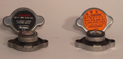
Radiator cap:
Keeps coolant in a
sealed system, allows overflow to exit and return as coolant expands
and contracts, but most importantly it raises the boiling point of the
coolant in the system by keeping the cooling system pressurized. Most
radiator caps for stock vehicles keep the system pressurized between
13-15psi. This can raise the boiling point depending on the mix of
coolant/water an additional 35-40 degrees. A 50/50 mix of anti-freeze
and water has a boiling point around 265 degrees. Add to that a
radiator cap that holds 13psi and now you have coolant that won’t boil
until 300 degrees .
There are areas
throughout the engine where the coolant circulates that become very
hot. So hot that it can boil coolant. Since we must have the coolant in
contact with the metal to perform it’s heat transfer duties we now have
a problem. Scenario: Radiator cap is weak (which we run into all the
time on Subarus). A weak radiator cap not holding pressure may not let
all of the coolant get hot enough to boil but there are areas within
the engine that are now boiling. Boiling coolant has air bubbles that
now keep the coolant from contacting the cylinder walls and other
extremely hot areas within the engine. This heat is more than the
engine and gasket were designed to withstand on a regular basis and
thus a situation that will accelerate the failure of the gasket.
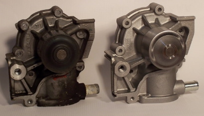
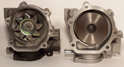
Flow of the coolant is
important also. To keep from boiling the hot coolant must be quickly
moved away from the hot cylinder walls up to the radiator so it can
release it’s heat. Below is a picture of a Subaru water pump and also a
quality Japanese aftermarket water pump. Although we for the most part
believe in genuine Subaru parts, here’s a case where genuine Subaru
part’s may not be the best choice. Note the stamped steel vanes on the
Subaru pump vs the quality cast and machined impeller on the Japanese
counterpart. The tight clearances and defined impeller vanes are very
efficient at moving coolant through your Subaru engine. (an interesting
side note that older Subaru water pumps were made nearly identical to
the pump on the right).
Another important part
of keeping the hot coolant flowing out to the radiator and away from
the internal hot spots in the engine is a high quality thermostat. I’ve
shown below the comparison between a generic aftermarket brand on the
left and a genuine Subaru thermostat on the right.
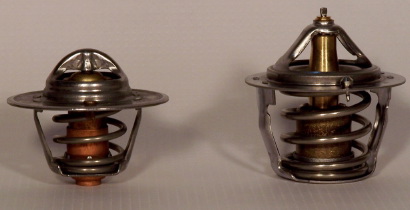
Note the Subaru version
has a much larger spring, larger diameter central area for coolant flow
and is made of steel and brass. The generic brand contains copper, a
big no no with Subaru. Subaru actually states that copper in a Subaru
cooling system is ill advised and may cause excessive electrolysis and
corrosion.
Even after trying to be diligent about
providing the best possible cooling for your Subaru you still may need
to cross the head gasket bridge some day.
|